 |
Charlotte Stonestreet
Managing Editor |
| Home> | DRIVES & MOTORS | >Brushless Motors | >BG motors with field-oriented control |
Editor's Pick
BG motors with field-oriented control
13 September 2018
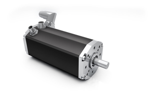
The integration of the power electronics in a brushless DC motor (BG motor) not only enables the motor to be controlled in a very simple and elegant manner, but also offers a large number of control algorithms that can be implemented, writes Dr. Bruno Basler, head of R&D predevelopment at Dunkermotoren.
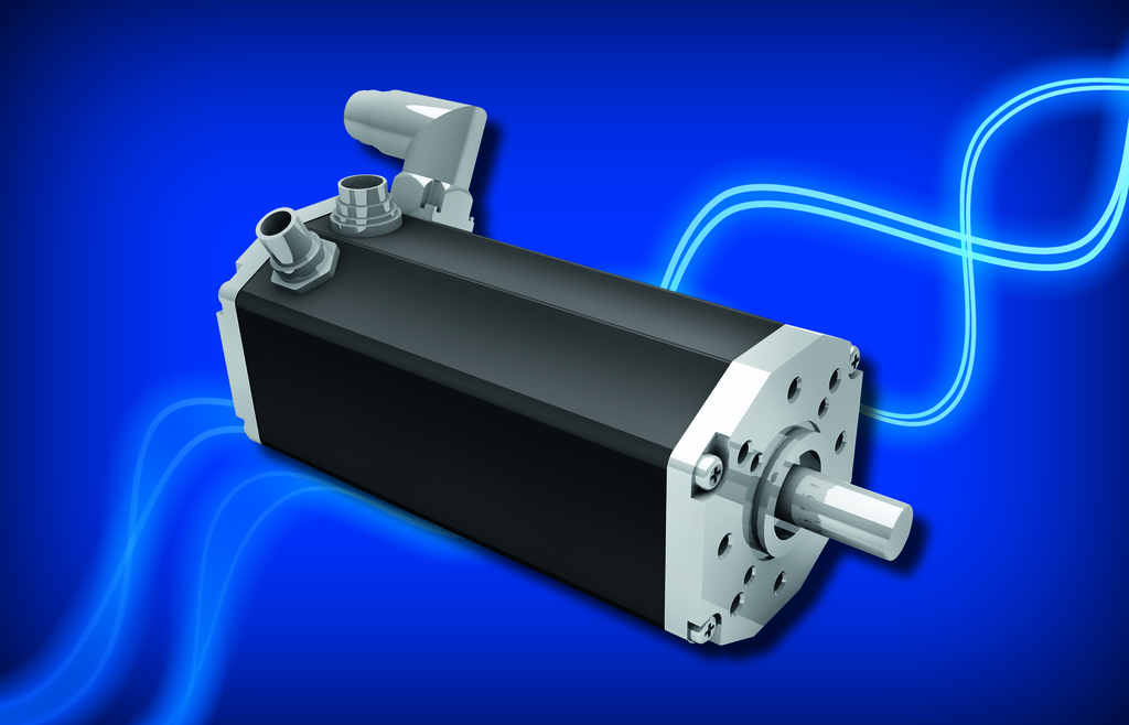
The state of the art is field-oriented control (FOC), based on the mathematical description of the motor and the conversion of alternating quantities into direct quantities. The FOC offers advantages for power electronics, improves the dynamic behaviour and delivers optimum torque.
From the control engineering point of view, the FOC is comparable to the control of a brushed DC motor. The typical behavior of a brushed DC motor (GR motor) is achieved by decoupling magnetic flux and torque. The basic concept of the FOC is the consideration of temporal momentary values. Thus, the electrical alternating variables of a three-phase motor are not treated as fixed in space but rotate with the rotor. This means that the three phase currents measured at the stator are converted into rotor coordinates. Since the reference system is static, the controller can operate with direct current quantities instead of alternating quantities.
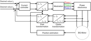
The direct quantities are divided into a field-forming (d) and a torque-forming (q) component. Since the magnetic flux in the air gap is generated exclusively by the permanent excitation, the stator currents have virtually no flux-forming components. Due to the surface magnets of the rotor, the setpoint for the field-forming current (Id) is set to zero. The output of the current controller represents the reference voltages in the rotor coordinates. To control the three-phase stator current, the FOC algorithm generates a three-phase voltage vector. The basis for this is the conversion of the rotor fixed d/q values into stator fixed α/β values. The conversion of the physical current into a rotation vector using the Clarke and Park transformations turns the torque and the magnetic flux into time-independent variables. An extended proportional-integral (PI) controller with the proportional gain and reset time parameters is used as the control algorithm. These parameters depend on the motor inductance, the winding resistance and the complete signal processing chain.
DC motors are designed in such a way that the magnetic flux in stator and rotor are offset by 90° to each other, whereby the motor generates maximum torque. FOC technology transforms motor currents into two-axis vectors that are comparable to those in a DC motor.
The process starts with a measurement of the three phase currents of the motor (i1, i2 and i3). Because the sum of the three current values is zero at all times, in practice only two of the three currents are measured and the value of the third current can be calculated from the measured values obtained. This results in an immediate reduction in hardware costs, as only two current sensors are required. With the information of the stator currents and the rotor angle, the values are transformed into a coordinate system in order to calculate the polar coordinates, consisting of magnitude and angle. This means that measured motor currents are mathematically transformed from a three-phase static reference system of the stator winding into a rotating reference system. The rotating system consisting of the d and the q component can be processed very easily by a PI controller. Similarly, the voltages to be applied to the motor are mathematically transferred from the d/q system of the rotor into a three-phase reference system. If a sinusoidal input current is supplied to the stator, a rotating magnetic flux is generated. The speed of the rotor is directly related to the rotating magnetic flux.
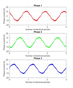
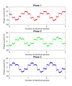
With the aid of pulse width modulation (PWM), the magnitude and angle values are converted into three-phase currents by controlling the inverter's high and low-side switches accordingly. With the FOC method, the PWM signals of the modulation are fed sinusoidally to the three-strand winding of the motor. Due to the basically finite switch-on and switch-off times of the power semiconductors, their control signals are artificially delayed in order not to cause a bridge short circuit when switching between positive and negative DC link voltage.
- Integrated control & electronics
- Tubular linear motors to replace pneumatic actuators
- Integrated amplifier & controller
- Hygienic linear motors
- Ultra-compact brushless DC motor
- Integrated controller option
- Precise, fast positioning
- Powerful, compact brushless rotary DC motor
- Optimal solutions for linear movement
- Incorporates power supply & all functions
- Enhanced Performance From Asynchronous Spindle Motors
- INTEGRATING MOTORS INTO MACHINE DESIGNS
- Brushless Servo Motors
- ESCON 36/3 EC
- Drive selection on the Internet with the maxon selection program.
- Off-the-shelf efficiency
- Maintenance reduced
- Solar tracking motors
- Less space, more power
- Ultra-compact brushless DC motor
